Copyright © 1999
Pioneer Magnetics, Inc.
|

Benefits of Power Factor Correction:
- 42% more output power.
- Lower input current (40% less).
- Automatic Wide Input Range from 85 to 264VAC.
- 3-Phase connected neutral current cancelled.
- Minimizes the harmonic distortion to ensure compliance to IEC555-2 limits Class A.
- Reduces EMI/RFI noise.
|
|
Summary:
- Pioneer Magnetics was the first to introduce the Power Factor Correction (PFC) circuit.
- This patented current sensing method was licensed to Unitrode (UC3854) as well as other semi-conductor companies and sold worldwide.
- Pioneer's PFC circuit provides power factor correction over the entire AC input range.
|
WHY POWER FACTOR CORRECTION (PFC)?

Copyright © 1999
Pioneer Magnetics, Inc.
|
This article, in a somewhat revised version, appears in the March 1999 issue of "Electronic Product News" (EPN).
The combination of active Power Factor Correction (PFC) with the modern switching power supply has resulted in unusually effective power conversion machines. PFC switching power supplies offer distinct, unique advantages not only to the ultimate user, but also for the Original Equipment Manufacturer and the world's power distribution system.
ADVANTAGES OF POWER FACTOR CORRECTION
>> Original Equipment Manufacturer
- Extremely compact with flexible form factor – 5KW in
5" x 5" x 15.5".
- Highest Power Density – 12.9 watts/in3 for 5KW.
- Lighter Weight – 14.8 lbs. for 5KW.
- Higher Reliability – Over 1,000,000 hours DMTBF. The Power Factor Correcting Front End reduces stress by supplying well-regulated DC to the main DC/DC power converter.
- Wide Range Operation – 85VAC to 264VAC. This reduces stocking problems for various AC line voltages.
- Higher Efficiency – to 91% overall at 48VDC.
>> User – The Customer
- Compliance with European IEC 555.
- Wide Range of AC Line Services – 85VAC to 264VAC.
- Worldwide reliable operation from unreliable rural or third-world power grids – power through voltage drops (brown-outs) that would shut down non-PFC power supplies.
- Greater Utilization of Existing AC Power Service – Unity Power Factor offers:
- Up to 50% more output power for a given AC service.
- Greater utilization of an existing factory or office power grid. A 120VAC 12 Amp service can support a 1,000W DC load instead of approximately 655W without Power Factor Correction.
- Lower line current/KW of output reduces copper losses of the electrical service.
- Significant reduction in required electrical supply capacity or a lower cost for a new or remodeled factory/office electric power grid.
- High efficiency – reduces electrical power and office air conditioning operating expenses.
>> Public Utilities – Power Grid
- Low Harmonic Content of PFC supplies reduces radiation from utility lines and eliminates interference with radio, television and other communication.
- More effective utilization of the world's electrical power pool:
- Utility power distribution grids are designed with finite electric current capacity. Broad use of Power Factor Correction would allow the world's power grids to deliver up to 30% more energy through the existing power distribution systems.
- Many public utilities offer financial incentives to businesses that use Power Factor Corrected electrical equipment.
POWER FACTOR DEFINED
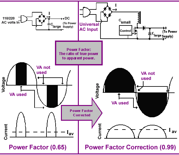
Power Factor is defined as the ratio of the actual power consumed by an alternating current device divided by the apparent power (RMS voltage x RMS current) concurrently drawn by the device. The actual and the apparent power are identical (Power Factor = 1), when the device current is of the same wave shape (sinusoidal) as the applied voltage and both voltage and current wave are in phase with each other.
If the current waveform is distorted, i.e. non-sinusoidal, the power factor will become less than unity.
THE SWITCHING SUPPLY POWER FACTOR PROBLEM
In switching power supplies, the problem lies in the input rectification and filter network. Figure 1 is a typical input circuit and its associated waveforms. As one can see, the input rectifiers can only conduct current when the AC line voltage exceeds the voltage of the input capacitor. The useful power increase from PFC is illustrated for a 12 ampere, 120 volt AC service. Typical non-PFC and PFC power factors are 65% and 99%, respectively.
|
Figure 1-a: Input Current without Power Factor Correction. |
| |
|
Figure 1-b: Typical Switching Power Supply Input Circuit. |
| |
Output Power = Iin x Vin x Efficiency x Power Factor
= 12 x 120 x 0.70 x 0.65
= 655W |
|
HOW PFC CIRCUITS OPERATE
Power Factor Correction circuits insure that the AC input current waveform is sinusoidal and in phase with the voltage waveform
(Figure 2). This means that all the power drawn from the power line is real power and not reactive power. The net result is that, for a given line current rating, the useful power drawn from the line is much higher than that supported by the traditional non-PFC switching power supply.
|
Figure 2-a: Input Current with Power Factor Correction. |
| |
|
Figure 2-b: PFC Input Circuit.
|
Output Power = Iin x Vin x Efficiency x Power Factor
= 12 x 120 x 0.70 x 0.99
= 998W |
|
PIONEER'S PFC PRODUCT LINE IS READY FOR YOU
More than a decade ago, Pioneer Magnetics, Inc. (PMI) recognized the inherent advantages of the PFC switching power supply. PMI became the first international, as well as American power supply manufacturer to shift all of its new AC/DC converter designs exclusively to PFC. This concentration has resulted in an unusually effective line of very compact high power PFC switchers. As an example, 20KW of redundant AC/DC power is offered on a 3U, 23" rack. Both three-phase (95% PF) and single phase (99% PF) active PFC are available in the standard 5" x 5" package.
Pioneer Magnetics, Inc. (PMI) was the first to introduce the Extended Line Voltage Range Power Factor Correction. This patented current sensing method was licensed to Unitrode (UC3854) as well as other semi-conductor companies and sold worldwide. |

